A Smarter Doorbell - Part 2
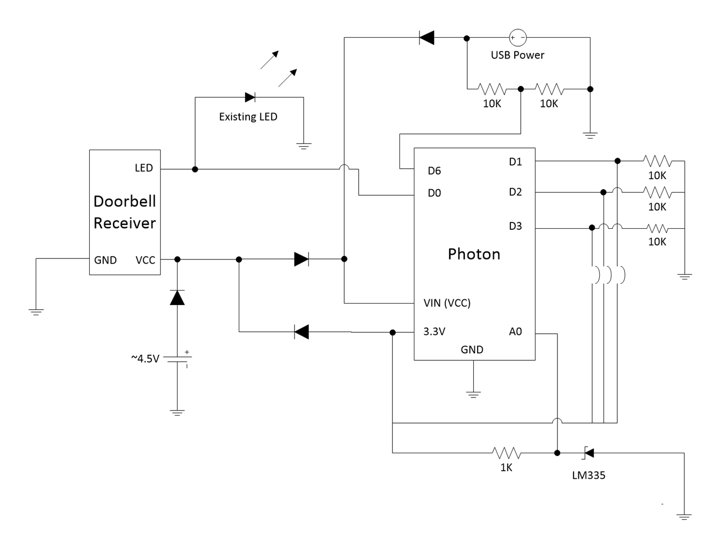
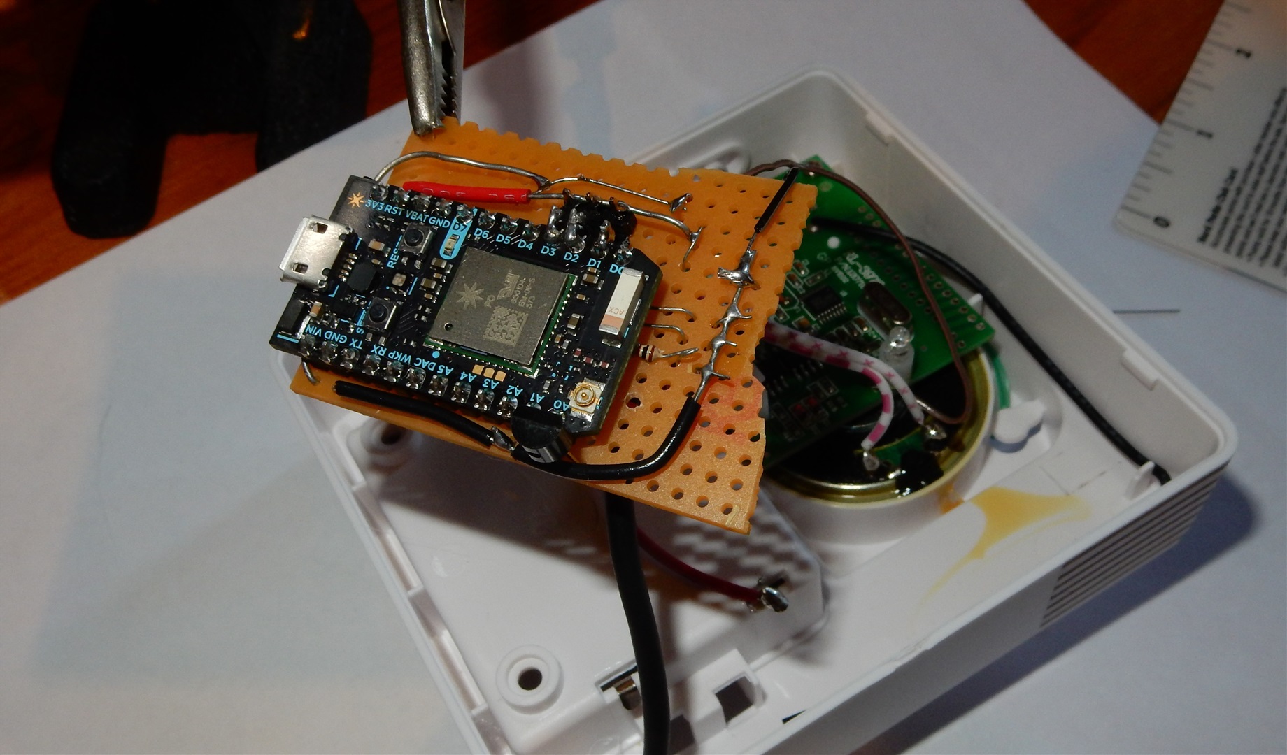
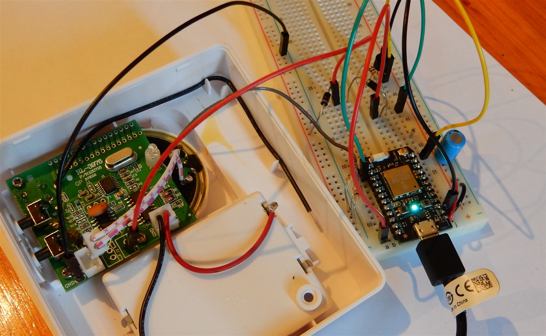
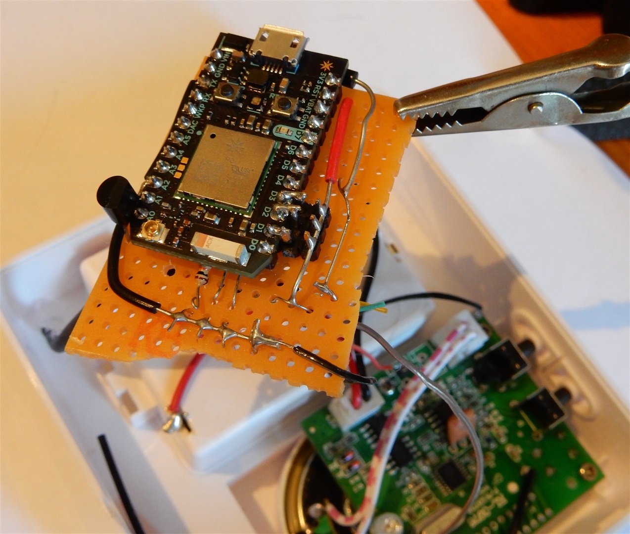
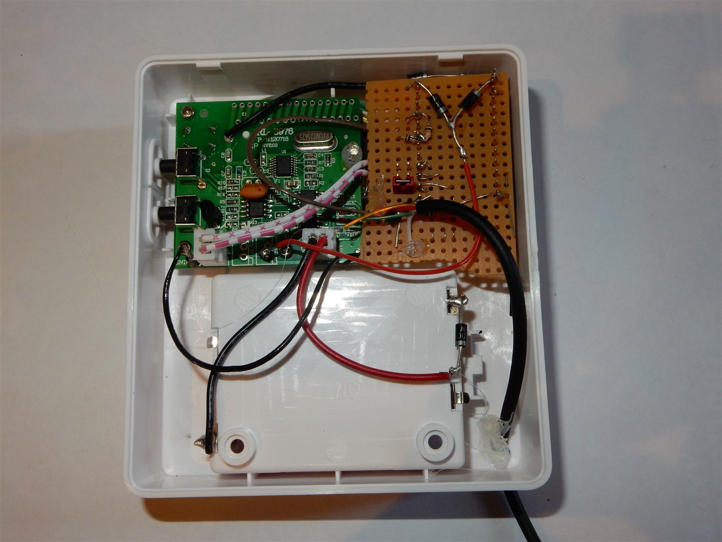
Published in Electronics Assembly of the improved home doorbell is finished! This project is about turning an existing doorbell into an IoT device so that, in future, other devices and systems can react when the doorbell rings. Read Part 1 if you missed it. The only extra sensor that made it in to this one was the LM335 temperature sensor. Really it was the only one that would be useful, and there wasn't much space in the case. This component wound up being more complicated to include than expected because it seemed to be a degree or two off the mark, so I used some leftover digital I/O pins to provide adjustment jumpers. A final breadboard test with all components before soldering: ... and the assembled project. Not the cleanest job I have to admit, but effective. Here's the schematic for the doorbell project (pretty simple really)... The code to drive the device is below. This project was really designed to be plugged in to the main most of the time, with the batteries being an optional backup power source. Therefore I haven't optimised it for long life on the batteries (the reason for the project happening in the first place was that I was tired of changing the batteries every few months). If I wanted it to run for a long time on batteries, I would have wired the Photon's wakeup pin so it could shut down completely until called for. If you're planning to copy this design verbatim, please keep in mind that it was designed with battery power as an afterthought so won't last anywhere near as long as it could per set of batteries. Also, there was a lot of I/O left over on the Photon. It would have been technically possible to pack a lot intelligence into the box if I could find useful things to add, and the space for them. A humidity sensor would be a candidate if I had to start over on this one. Now that we have a doorbell that can tell the the Internet when it rings and what the temperature at home is, the next step is to pull the data down to a mobile application or web page. The final part of this series will be making use of Particle's web API to utilise the IoT aspect of the project and put the information where we can see it.The extra sensor
Assembly
Schematic
Code
/**
 *  Simple program to publish an event when an external pint goes high - in this case a LED that blinks when the doorbell is ringing.
 *
 *  Requires Photon firmware 0.4.7+
 **/

const int LED_INPUT = D0;
const int LED_OUTPUT = D7;
const int BAT_INPUT = D6;

const int LOCKOUT_TIME = 15000;
const long WIFI_LIVE_TIME = 30000;
const long TEMP_READ_INTERVAL_MAINS = 30000;
const long TEMP_READ_INTERVAL_BAT = 60000 * 30;

const int TEMP_PIN = A0;
const float ANALOG_REF_VOLTAGE = 3.35; //my Photon's 3.3V regulator outputs 3.35V
const float KELVIN_BASE_TEMP = 273.15;
const int CALB_N2_PIN = D1;
const int CALB_N1_PIN = D2;
const int CALB_P1_PIN = D3;

bool notifyEnable = true;
bool wifiEnabled = true;

Timer lockoutTimer(LOCKOUT_TIME, unlock);
Timer wifiShutdownTimer(WIFI_LIVE_TIME, stopWifi);
Timer tempReadTimer(TEMP_READ_INTERVAL_MAINS, readTemp);

void setup() {
    pinMode(LED_INPUT, INPUT);
    pinMode(LED_OUTPUT, OUTPUT);
    pinMode(BAT_INPUT, INPUT);

    pinMode(TEMP_PIN, INPUT);
    pinMode(CALB_N2_PIN, INPUT);
    pinMode(CALB_N1_PIN, INPUT);
    pinMode(CALB_P1_PIN, INPUT);

    Serial.begin(9600);

    tempReadTimer.start();
    if(isRunningOnBattery()) {
        wifiShutdownTimer.start();
    }
}

void loop() {
    int status = digitalRead(LED_INPUT);
    digitalWrite(LED_OUTPUT, status);
    if(status && notifyEnable) {
        //Disable event publishing, publish and start time to reactivate publishing
        notifyEnable = false;
        lockoutTimer.start();
        wifiShutdownTimer.stop();

        if(!wifiEnabled)
        {
            WiFi.on();
            wifiEnabled = true;
        }
        while(!WiFi.ready())
        {
            delay(500);
        }

        Particle.publish("doorbell",NULL,60,PRIVATE);
        Serial.println("Doorbell pressed");

        if(isRunningOnBattery()) {
            wifiShutdownTimer.start();
            Particle.publish("runningOnBatt",NULL,60,PRIVATE);
        }

    }
    delay(333);
}

bool isRunningOnBattery()
{
    if(digitalRead(BAT_INPUT) == LOW)
        return true;
    return false;
}

/**Re-enable publishing of doobell event **/
void unlock() {
    notifyEnable = true;
    lockoutTimer.stop();
}


void stopWifi() {
    wifiShutdownTimer.stop();
    wifiEnabled = false;
    WiFi.off();
}

/**
 * Reads and reports the current temperature in celcius, and adjust duration of temperature read timer to suit battery/mains power.
 */
void readTemp() {
    //Read temperature
    int val = analogRead(TEMP_PIN);
    float temp = calcTemp(val);
    Serial.print("Temperature: ");
    Serial.println(temp);

    wifiShutdownTimer.stop();

    //Report temperature
    if(!wifiEnabled)
    {
        WiFi.on();
        wifiEnabled = true;
    }
    while(!WiFi.ready())
    {
        delay(500);
    }
    Particle.variable("temperature", temp);

    //Set next read interval
    if(isRunningOnBattery()) {
        tempReadTimer.changePeriod(TEMP_READ_INTERVAL_BAT);
        wifiShutdownTimer.start();
    }
    else {
        tempReadTimer.changePeriod(TEMP_READ_INTERVAL_MAINS);
    }
}

/**
 * Calculates the temperature in degrees celcius for an LM335 module output, using CALB_*_PIN to adjust for calibration errors in hardware
 */
float calcTemp(int analogValue)
{
    int adjust = 0;
    if(digitalRead(CALB_N2_PIN) == HIGH) adjust = -2;
    if(digitalRead(CALB_N1_PIN) == HIGH) adjust = -1;
    if(digitalRead(CALB_P1_PIN) == HIGH) adjust =  1;

    float volts = ANALOG_REF_VOLTAGE / 4096 * analogValue;
    float tempK = volts * 100;
    Particle.variable("tempAdjust", String(adjust));
    Serial.print("Temperature adjustment: ");
    Serial.println(String(adjust));
    return tempK - KELVIN_BASE_TEMP + adjust;
}
Limitations & Improvements
What next?
